Applying SSAO to scenes

The spinning Buddha (but you can’t see him spin here)

This has been a topic of interest for such a long time for me, but I finally got screen-space ambient occlusion working in my engine. Click here to see it in action! As with most graphics rendering techniques, there are many ways to skin a cat, and SSAO is full of them. I have read through so many articles on SSAO, looking to find something that works for me, and that is easy to understand and refine. Any approach you take may or may not work immediately, based on what already know and what resources you have to handle it.

Ambient occlusion is an easy concept to understand. To put it simply, concave areas, such as the corners of a room, will trap some rays from any light that shines on it, so the ambient light is somewhat darker than in other areas. Used in graphics rendering, this can really make it easier to see depth in different spaces, and it makes objects “pop” from the scene.

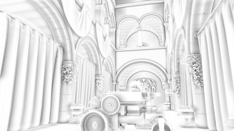
SSAO render target only

Original SSAO render target

The factors involved in computing ambient occlusion are easy to grasp, but I still have trouble breaking down the equations used in some of the approaches. Admittedly I am not very sharp on integration in math, which comes into play for many rendering techniques. But at least my linear algebra is good enough, so I just need to work in those terms to find the approach that works well for me. So I finally came to this article on GameDev, which, true to its title, was easy to figure out and works well for nearly all situations. It includes an HLSL shader that can be applied with few modifications.

To avoid repeating much of what the article says, this SSAO technique requires three important sources of data: normals in view space, positions in view space, and a random normal texture. The random normals reflect 4 samples picked from a preset group of textured coordinates (neighboring samples) which are rotated at fixed angles. The formula in the article attenuates the occlusion linearly, but you can choose to put your own formula if you want a quadratic attenuation, or cubic, etc.

Tweaking the results

A few changes were made to the original shader code to be compatible with my program. First, I don’t have a render buffer that stores view-space position, so the getPosition function needed to be replaced. We can reconstruct world space position from depth using the inverse of the camera’s view and projection matrix, and to get it into view space coordinates, multiply it with a view matrix:

float3 getPosition(in float2 uv)
{
	float depth = tex2D(depthSampler, uv).r;

	// Convert position to world space
	float4 position;

	position.xy = uv.x * 2.0f - 1.0f;
	position.y = -(uv.y * 2.0f - 1.0f);
	position.z = depth;
	position.w = 1.0f;

	position = mul(position, invertViewProj);
	position /= position.w;

	// Convert world space to view space
	return mul(position, ViewMatrix);
}

Probably not the fastest way to get view space from depth, but this code is written with readability in mind. The output image should be four different-colored rectangles evenly dividing the screen, which are the float values of the positions as color. What these colors are depend on the coordinate system you’re using (which is important to know as we’ll soon find out).

After this, I still noticed that the ambient occlusion output seemed to be right, but the values are inverted, so I get a grayscale negative of what is expected. So just subtract the final occlusion value from 1, and we’re good to go:

ao /= (float)sampleKernelSize;
return 1 - (ao * g_intensity);

But why do we need to do this? The reason is that the coordinate system used in XNA is right-handed, while the coordinate system in Direct3D is left-handed. The Z-axis usually points to the camera in XNA, meaning that the positive Z values are behind you, but in Direct3D they lie in front of you. The article was written with DirectX in mind, so users of XNA (and OpenGL if you choose to port the code) will have to invert the occlusion term when it’s returned. This corrects the output given from the normals flipped the other way in view space.

Finally, I removed some of the calculations involved in computing the occlusion, which are the bias and occlusion intensity. The width of the bias didn’t really do anything that I can see any change, and the intensity has been moved out of the the occlusion function and done once in the very last line, which gives the same results as repeating the multiplication by the intensity for each sample.

Final considerations

Your mileage may vary with this shader. To get the best results you’ll have to experiment in tweaking the parameters. The radius variable would work well between values of 2 and 10, depending on how much you scale your objects. Values much higher than this will be expensive to compute. The occlusion is best seen with the intensity set between 0.5 to 1.5, and the distance scale kept low, between 0.05 and 0.5.

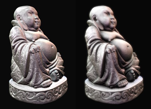
SSAO comparison

Left: without SSAO. Right: with SSAO and bloom

Of course, you may want to apply your own blur filter to remove the noise from the AO render. This noise pattern is from the random normal texture, and it stays fixed to the screen when the camera moves. I was able to get reasonable framerates with a full-screen render and a Gaussian blur applied to the AO. Some light “halos” are visible as a result from the blur, but they are not large enough to really distract from the view. What’s especially important to know is that the normals from your normal map must be correct in order to get good results, otherwise objects will be darkened in odd places. But that goes without saying that we’d already notice strange lighting with incorrect normals.

Sources

XNA Parallel-split shadow maps

Parallel-split shadow maps are here. Had some struggles with getting it to work today and yesterday. It made the Directional Lighting class huge, but I will factor it out later. As with the previous shadow mapping scheme, it uses the depth data of the G-Buffer so no geometry is re-rendered for the shadow map projection phase.

This method that takes advantage of the G-Buffer in deferred rendering is, perhaps surprisingly, called forward shadow mapping. It compares the depths between the buffer at camera view and the buffer at the light’s view after it’s transformed with its projection matrix. Then it gets multiplied by the light term, and finally the diffuse color. I decided to skip blurring the shadow map but that can be done in an extra pass if needed.

Forward Shadowing

(By the way, in the above webpage, the links to the blurred images are incorrect. Add “blur” before the extension to view the blurred examples in full size ie. “main512blur.jpg”.)

We still need to render all those scenes at different distances for all the frustum splits. I am using 1024×1024 render targets. That took a toll on the busy Sponza scene 😦 It’s now from 65 fps down to 45. Sparser scenes are still plenty fast, though- the scene in this video usually runs at over 100fps without a screen recorder on.

At first I decided to split up the shadow renders into several passes. Not actual effect passes, but repeating the same rendering technique several times. For each pass, the shader would take in different parameters for the light’s view matrix, split distances, and corresponding depth map. Initially this rendered all shadow maps at the same starting depth (the near distance). I noticed an overlapping effect in the lighting, because the closest split was very bright and the farther ones were darker.

This was a side effect of the light buffer accumulating color values, so no, this won’t work. The shadow renders need to be split. A basic depth conversion formula can convert the depth map to linear view space, simply being this one as found on this depth of field tutorial:

float linearZ = (-camNear * camFar ) / (depthVal – camFar)

Also, since camFar is always going to be 1, we can just drop the multiplication for the numerator.

Eventually I was able to split the distances well but the shader still wasn’t clipping out of bound pixels very well. Also it had some strange rendering bug where the closer maps were showing dim shadows over the farther ones and clamping at odd angles. This was more apparent when the camera was completely facing opposite of the light’s direction.

Finally I just bit the bullet and put all of the depth map rendering in a single pass. This fixed everything as we now don’t have brightness accumulation over the split regions and the view matrices are perfectly lined up. The shader is still disorganized however, with more branching in some places, more constants being loaded, as well as throwing in all four of the depth map textures to sample in.

Ideally I would like to have reduced the need to select render textures or texel offsets by doing multiple light view matrix transformations at once. One time I was thinking, “it would be great if you could output multiple positions at once on the vertex shader, just as you can with render targets on the pixel shader”. Then I quickly realized that’s what the geometry shader does. Derp. Too bad it’s not available for XNA use. MJP says it brings crappy performance anyways.

So here’s the start of my somewhat odd parallel-split shadowing function. There are several different ways to get the trick done, and this is how I managed it.

float shadow = 1.0f;
if (shadowing >= 1)
{
    float shadowIndex;
    if (linearZ > cascadeSplits.z)
    {
        shadowIndex = 3;
    }
    else if (linearZ > cascadeSplits.y)
    {
        shadowIndex = 2;
    }
    else if (linearZ > cascadeSplits.z)
    {
        shadowIndex = 1;
    }
    else
    {
        shadowIndex = 0;
    }

    float4 shadowMapPos = mul(position, lightViewProj[shadowIndex]);
    float2 shadowTexCoord = shadowMapPos.xy / shadowMapPos.w / 2.0f + float2( 0.5, 0.5 );
    shadowTexCoord.y = 1 - shadowTexCoord.y;

    float shadowDepth = 0;
    float occluderDepth = (shadowMapPos.z / shadowMapPos.w) - DepthBias;

    if (linearZ < cascadeSplits.x)
    {
        shadowDepth = tex2D(shadowMapSampler[0], shadowTexCoord).r;
        shadow = LinearFilter4Samples(shadowMapSampler[0], 0.3f, shadowTexCoord, occluderDepth);
    }
    else if (linearZ < cascadeSplits.y)
    {
        shadowDepth = tex2D(shadowMapSampler[1], shadowTexCoord).r;
        shadow = LinearFilter4Samples(shadowMapSampler[1], 0.3f, shadowTexCoord, occluderDepth);
    }
    else if (linearZ < cascadeSplits.z)
    {
        shadowDepth = tex2D(shadowMapSampler[2], shadowTexCoord).r;
        shadow = LinearFilter4Samples(shadowMapSampler[2], 0.3f, shadowTexCoord, occluderDepth);
    }
    else
    {
        shadowdepth = tex2D(shadowMapSampler[3], shadowTexCoord).r;
        shadow = LinearFilter4Samples(shadowMapSampler[3], 0.3f, shadowTexCoord, occluderDepth);
    }
}

This code resides in the same function used to calculate directional lighting, and each light can be set to cast shadows or not. I recommend using a very low number of lights as the depth map rendering makes this process expensive quickly. Besides, unless you have some weird sci-fi setting with several suns, it just looks plain wrong when you have many directional shadows going on.

As you can probably tell, I am using four different depth maps and four parallel splits for the whole render. There’s some branching involved, unfortunately, as I can’t pass anything but literals to sampler array indexes. However I was able to replace another if-else statement with just adding up booleans as numbers to get the index for the light view matrix. This code:

    float shadowIndex;
    if (linearZ > cascadeSplits.z)
    {
        shadowIndex = 3;
    }
    else if (linearZ > cascadeSplits.y)
    {
        shadowIndex = 2;
    }
    else if (linearZ > cascadeSplits.z)
    {
        shadowIndex = 1;
    }
    else
    {
        shadowIndex = 0;
    }

was condensed into the code you see near the top of the last example:

    float shadowIndex = (3 -
        (linearZ < cascadeSplits.x) + (linearZ < cascadeSplits.y) +
        (linearZ < cascadeSplits.z));

Edit: Turns out that it IS possible to do texture sampling with variable indexes. Just use tex2Dgrad instead of tex2D to use the samplers, and the program will happily compile the code with variables passed for the shadowMapSampler array. We won’t need to apply a rate of change to the geometry, so the last two paramteres are changed to zero.

This gets rid of all the if-else syntax, and now the entire shadow lookup code is shortened, and looks much better. The code is now almost 1/3 its original size and there are less comparisons to do.

float shadow = 1.0f;
if (shadowing >= 1)
{
    float shadowIndex = (3 -
        (linearZ < cascadeSplits.x) + (linearZ < cascadeSplits.y) +
        (linearZ < cascadeSplits.z));

    float4 shadowMapPos = mul(position, lightViewProj[shadowIndex]);
    float2 shadowTexCoord =
        shadowMapPos.xy / shadowMapPos.w / 2.0f + float2( 0.5, 0.5 );
    shadowTexCoord.y = 1 - shadowTexCoord.y;

    float shadowDepth = 0;
    float occluderDepth = (shadowMapPos.z / shadowMapPos.w) - DepthBias;

    shadowdepth = tex2Dgrad(shadowMapSampler[shadowIndex], shadowTexCoord, 0, 0).r;
    shadow = LinearFilter4Samples(shadowMapSampler[shadowIndex], 0.3f,
        shadowTexCoord, occluderDepth);
}

Basically, I grouped the far distances of the first three splits into a Vector3, and then compare them to the linear depth output for that pixel. X is closest, and Z is the farthest. For four different splits, 3 will be the maximum index. It follows that if linearZ is closer than the first split, the same is also true for the second and the third, so we start by adding up the total true statements and then subtracting that total from the maximum. If all statements are false, then the last split and light view matrix will be used, so the index stays at 3.

Everything else is mostly standard shadow mapping work, and a simpler to read branching statement follows that determines what depth map to compare and sample from. But if there’s a way to clean it up some more, I’d like to know. The ComputeShadow4Samples is an adaptation of the manual linear filtering function available here. It is necessary for filtering these shadow maps since they are a Single 32 bit float format, and thus can only be interpolated after the shadow comparison has been determined. “0.3” is just a way to attenuate shadow darkness so they don’t appear completely dark.

From here on the the resulting pixel color just gets multiplied with the brightness output of the directional light that casts the shadow. I don’t know whether it’s more accurate to replace brightness with the shadow coefficient instead of multiplying brightness with shadow, but it still looks fine either way. So there you have it- directional lighting with the G-Buffer and shadow mapping in one fell swoop.

Cutting down on garbage collection

Another big update for the Meteor Engine – now it does almost zero garbage creation at runtime. The only exceptions are getting the current mouse and keyboard input- these always allocate memory- but since these are PC-only inputs and the PC hardly hiccups with a single 1MB collection, these exceptions are a non-issue. I figured that my engine needed a good tuning up in order to avoid any unexpected stalls, especially if I plan to port it to Xbox 360. And better to do it now before the engine becomes any more complex.

Figuring out how to optimize for garbage collection has really helped me in writing more efficient C# code. Now, I’ll tell you that prior to using XNA, I have never ever coded in C# before. I’ve mainly been a C++ guy. And I only really got serious with trying out XNA this July, which means I have just about 5 months in seeing how the C# language works, with all its peculiarities of value types, reference types, and memory allocation. So with that said, I am far from the best guy to talk about how everything about C#, its CLR and .NET components work. Still, I have learned a lot so far, thanks to the XNA veterans at the App Hub Forums and also some of their respective blogs, and I will be learning a lot more in the time to come.

As far as reducing the creation of garbage goes, it wasn’t actually too difficult. There were a few cases where I had to write my own functions to circumvent others that really had no way of avoiding memory allocation, but it served me to understand how to do these things on my own. I have tracked down several major causes of garbage collection in my engine:

  • String creation (usually for debug output)
  • Updating mesh transformation matrices for rendering
  • Creating arrays and lists immediately as needed instead of storing them for later
  • Calculating BoundingBoxes with CreateFromPoints() on each frame for culling and rendering
  • Using BoundingBox.GetCorners()  to update the view frustum for directional lights

So not much to do, though of course some involved more work than others to fix. I had to discover these issues one by one, and I started with the one that’s the most obvious for causing this sort of problem.

Creating strings

This one was pretty straightforward, as string manipulation is one of the most reported causes of memory allocation in XNA’s realtime applications. Best to use the SpriteBatch.DrawString more carefully, but luckily with all the stern warnings on using Strings and StringBuilder objects, there are a few existing code bases that you can use to help you out. I eventually took to using Gavin Pugh’s garabage-free StringBuilder extension for formatting numerical values. To make sure I’d get rid of all the string problems, I stopped rendering and updating all other areas of the program. Then I simply put the class into my engine code, re-wrote a few lines in the debug display function, and it was ready to go.

Mesh bone transformations

Now came the first challenge, making the rendering code garbage-free. Here’s where GC.GetTotalMemory was going nuts for, as 1 MB of trash was being scooped up almost every second. As I said before, this didn’t create any noticeable stalls on the PC, but I’m not gonna take any chances with the memory-limited Xbox. So with paring down and commenting out code here and there, I found out that copying the bone transforms to a new Matrix array was not the best way to go. Instead of creating new matrices, I pre-allocated a Matrix array for all the bones in the mesh, and updated them there. Here’s the before code:

		/// <summary>
		/// Draw all visible meshes for this model.
		/// </summary>

		private void DrawModel(InstancedModel instancedModel, Camera camera, string tech)
		{
			// Draw the model.
			Matrix[] transforms = new Matrix[instancedModel.model.Bones.Count];
			instancedModel.model.CopyAbsoluteBoneTransformsTo(transforms);

			foreach (ModelMesh mesh in instancedModel.VisibleMeshes)
			{
				foreach (ModelMeshPart meshPart in mesh.MeshParts)
				{
					Matrix world = transforms[mesh.ParentBone.Index] * instancedModel.Transform;

					/* .... */
				}
			}
			// End model rendering
		}

Here’s the improved version:


		private void DrawModel(InstancedModel instancedModel, Camera camera, string tech)
		{
			// Draw the model.
			instancedModel.model.CopyAbsoluteBoneTransformsTo(instancedModel.boneMatrices);

			foreach (ModelMesh mesh in instancedModel.VisibleMeshes)
			{
				foreach (ModelMeshPart meshPart in mesh.MeshParts)
				{
					Matrix world =
						instancedModel.boneMatrices[mesh.ParentBone.Index] * instancedModel.Transform;

					/* .... */
				}
			}
			// End model rendering
		}

The array of boneMatrices is easily allocated after the model has been loaded successfully.

boneMatrices = new Matrix[model.Bones.Count];

This allows for better separation of the data and the functions that process it. By the way, foreach loops shouldn’t be causing a problem with the iteration in this case, as the newer version of the CLR runs through foreach loops much better, as explained in this article about memory profiling. Nothing really should have to move to the heap here.

List and array creation

This one was just plain dumb on my part. Most of the garbage-creating arrays had to do with the fact that my modular rendering system depended on arrays to pass around render targets as inputs and outputs. As one shader component passes the completely drawn render targets to the next (usually one but the GBuffer needs to pass several), I was initializing a brand new array for the render targets to be returned by the OutputTargets property, on every frame. To my surprise, this wasn’t making the GC memory output tick as fast as others, but it still was a very obvious fix.

All shader components are derived from the BaseRendere class, where OutputTargets comes from, but I kept overriding that property. Then I realized, well I just have base class to work with right there, why didn’t I just use that? So now I pre-assigned all the outputs to keep always them ready.

		// GBuffer example

		public override RenderTarget2D[] OutputTargets
		{
			RenderTarget2D[] rtArray =
			{
				normalRT, depthRT, diffuseRT
			}
			get
			{
				return rtArray;
			}
		}

Now with no garbage:

		// In the BaseRenderer class

		public virtual RenderTarget2D[] OutputTargets
		{
			get
			{
				return outputTargets;
			}
		}

		// In constructor for GBuffer shading

		outputTargets = new RenderTarget2D[]
		{
			normalRT, depthRT, diffuseRT
		};

Also, passing multiple render targets as a series of parameters was also not playing well with memory. When setting them, just stick them all into a RenderTargetBinding structure instead.

Bounding boxes and mesh culling

Here were more unnecessary creations of new objects and referencing other ones for calculations. In creating temporary BoundingBoxes to make new transformed ones to go along with the mesh transformations, we are able to cull meshes easily. But those “temporary” boxes can be made less temporary if we just pre-allocated them into the custom model objects. Here is how my code looked like before:

/// <summary>
/// Cull meshes from a specified list.
/// </summary>

private void CullFromModelList(Scene scene, Camera camera, Dictionary<String, InstancedModel> modelList)
{
	// Pre-cull mesh parts

	foreach (InstancedModel instancedModel in modelList.Values)
	{
		int meshIndex = 0;
		instancedModel.VisibleMeshes.Clear();

		foreach (BoundingBox box in instancedModel.BoundingBoxes)
		{
			BoundingBox tempBox = box;
			tempBox.Min = Vector3.Transform(box.Min, instancedModel.Transform);
			tempBox.Max = Vector3.Transform(box.Max, instancedModel.Transform);

			// Add to mesh to visible list if it's contained in the frustum
			tempBox = BoundingBox.CreateFromPoints(tempBox.GetCorners());

			if (camera.Frustum.Contains(tempBox) != ContainmentType.Disjoint)
			{
						instancedModel.VisibleMeshes.Add(instancedModel.model.Meshes[meshIndex]);
			}

			meshIndex++;
		}
		// Finished culling this model
	}
}

Now, the InstancedModel class will just keep a second array of BoundingBoxes to complement the first array of pre-transformed boxes, leaving me to just reference the model for culling instead:

		private void CullFromModelList(Scene scene, Camera camera, Dictionary<String, InstancedModel> modelList)
		{
			// Pre-cull mesh parts

			foreach (InstancedModel instancedModel in modelList.Values)
			{
				int meshIndex = 0;
				instancedModel.VisibleMeshes.Clear();
				
				foreach (BoundingBox box in instancedModel.BoundingBoxes)
				{			
					instancedModel.tempBoxes[meshIndex] = box;
					instancedModel.tempBoxes[meshIndex].Min = 
						Vector3.Transform(box.Min, instancedModel.Transform);
					instancedModel.tempBoxes[meshIndex].Max = 
						Vector3.Transform(box.Max, instancedModel.Transform);

					// Add to mesh to visible list if it's contained in the frustum

					if (camera.Frustum.Contains(instancedModel.tempBoxes[meshIndex]) != 
						ContainmentType.Disjoint)
					{
						instancedModel.VisibleMeshes.Add(instancedModel.model.Meshes[meshIndex]);
					}

					meshIndex++;
				}
				// Finished culling this model
			}
		}