Starting to add terrain

Here is something that I felt was long needed- the ability to render terrain from height maps. I finally got around to making a simple class for one (based on Riemer’s XNA example). Thought it’s far from perfect it’s a decent start. Heightmaps are currently only generated from imported grayscale images, and always at full resolution. They use different shaders than the other objects, but made adaptable for deferred rendering. Consequently, they are also rendered in their own Draw function.

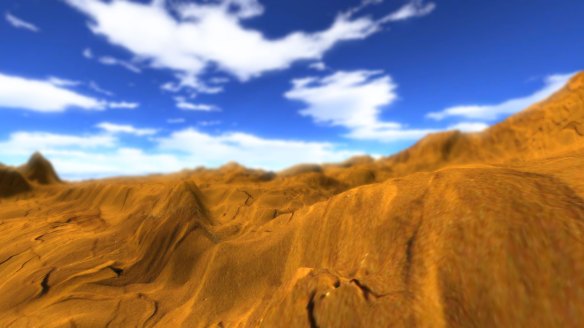
So there’s not much to the terrain right now. I just picked a texture and went with it. Instead of grass, which is commonly used, in my first attempt I decided to make a simple desert scene with a sand texture.

map1

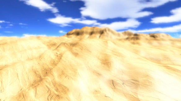
The original color of the sand looks too strong, making the landscape look somewhat alien, which is not what I’m looking for. I went into Photoshop to improve the texture’s brightness and contrast, and tried the result.

map2

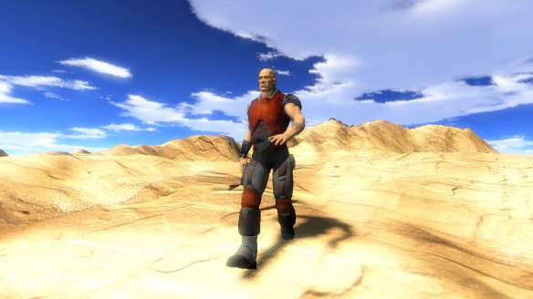
At least the ground looks a lot better now. With the help of some XNA sample project code, I made the Dude model walk on the surface of the terrain. This screenshot also shows the tri-planar mapping that I applied to stop textures from stretching on steep surfaces. Here’s a video of the terrain after having made those fixes. (The disappearing dude problem has since been fixed, it was a matter of correctly creating a bounding sphere for it).

map3

The tri-planar mapping was surprisingly simple to apply. These two articles give a good explanation of how it works.

While the Dude is skating and moonwalking all over the surface, it’s not a true physics feature, because there’s no real constraints like stopping him from walking on steep slopes or passing through other objects. But it would be useful for placing objects on the ground.  As it is, though, I might as well release this game as “Big Rigs: Dude Edition” and accept the consequences. (At least I clamped the heights at the terrain edges so the character doesn’t spazz all over the place!)

From here I’ve realized that optimizations for heightmaps are greatly needed for many cases. I’m using a 512×512 image for the terrain, which end up being a lot of triangles for the vertex buffer. Previously I mentioned how rendering a bunch of geometry is my newfound bottleneck from instancing many objects- well, now it’s in the terrain. My light pre-pass rendering has dropped to 25-30 FPS, and deferred rendering at 40-50 FPS. Also, these framerates are without rendering it in the shadow maps! I can’t imagine how much slower it will be if I did render the terrain for self-shadowing. As of now, it looks decent without self-shadowing. As I further work on the scene culling (it currently does brute-force culling for instances), the terrain rendering will improve as I gradually adapt the culling techniques.

Breaking the terrain into chunks is a an obvious improvement, which would work just with brute-force culling. But quadtress and LOD meshes are the goal here. I looked at ROAM-based techniques for LOD rendering and it looks pretty good, but I think I will use geometric clipmapping, which looks easier to understand implement.

My approach will be starting out just with a simple, 2-level geo clipmapping scheme, rendering a small chunk of terrain around the camera at full resolution, and the outer clipmap at 1/2 the detail of the original. The sample terrain I’m using is not too big (513×513) so using more than 5 levels seems like overkill. However, I plan to eventually get larger terrains working, for over 4 square kilometers. The reason for that is, well, I already have a game in mind for it 🙂 I will be developing it together with the engine.

Poisson Disc shadow sampling – ridiculously easy (and good looking too)

I did not know why I didn’t implement this sooner. I know before I said that I was happy enough with the shadows that I will not focus on any more major improvements, but looks like I lied 😛 So presenting, Poisson disc shadow filtering. Basically, I ditched the 4-sample manual linear filter code to go back to the basics and added Poisson filter. There’s already quite a few blog articles that talk about out, not the least which is useful for shadow mapping. This shadow mapping tutorial (but with GLSL code) covers it in an easy to understand way.

For that reason, I won’t go into the details, but generally speaking, you take a number of samples from a given area that are spaced as evenly as possible. Then you blend the opacity of each sampled shadow to get the result. It eliminates the “pixely” look well while avoiding too much random distribution. Here’s the handy tool I used to generate a bunch of sample locations, which I plugged into the shader code. I am fine just using this for static values, and not bother with coding my own generation algorithm for this.

Here’s a few screenshots with Poisson filtered cascaded shadow mapping and was surprised at the results. The simplicity of using a standard shadow map and jittering in a bunch of directions makes shadow edges appear nice and soft at a glance.

Poisson disk sampling

Here is one with the lighting and shadows only, before adding gamma correction:

Poisson disk sampling

And one showing point lights interacting with the shadow color. I find this one good enough to add to the front page of my Codeplex site.

Poisson disk sampling

All these screenshots use a 16-tap filter. I could’ve used more, but it does require a texture lookup for each sample and I hit the shader instruction limit beyond 20 samples. The blocky artifacts are still present when seen up close, but they are definitely better than the artifacts you get from PCF shadow mapping. The way in which the samples clump together give a good illusion of out-of-focus areas that give shadows their soft appearance.

There are also other ways to apply the filter, most commonly rotated Poission disc for each texel, or randomize the sample lookup. I didn’t use these for the following reasons- I didn’t see much of a benefit to rotate the disc each time, as the pattern is already hard to discern. With random lookups, the point is to produce noisy gradient edges instead of banded edges. This is expensive to do when you add up all the samples, and I actually think the noisy edges look like crap. The noise pattern moves when the camera moves, which is very distracting. It’s almost as bad as the shimmering effect, and I prefer still looking shadows.

So here, I think, is the easiest approach to approximating soft shadows, while still looking very good. No more attempting to use variance shadow maps or exponential shadow maps… they have their own pitfalls. All you need is a simple shadow map and a bunch of (well-placed) samples to get going.

Game, meet engine

Hey guys, this time the update will be short, but some significant updates that they are. I have successfully compiled a library from my engine that would work in other projects more transparently. In fact, I was able to get the Meteor Engine to run in Bubble Tower.

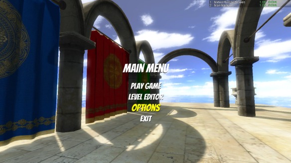
But hey, check it out, more exciting game screenshots! Here’s an example of the Meteor Engine running in it.

Menu screen with 3D render

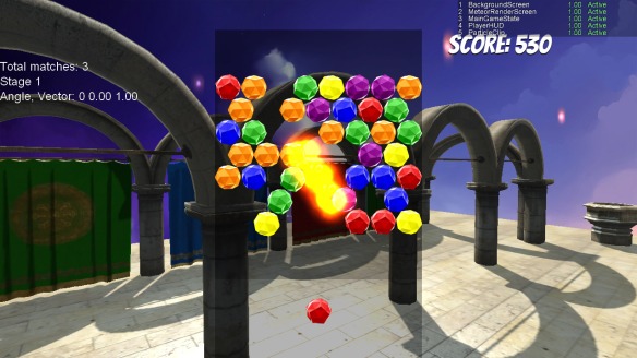
Also, particle effects! That is actually not part of the engine (a lot of things in the game still rendered ad-hoc), but it could well be.

Note that I’m using a 2D sprite image for the background here. I have deliberately made the rendering engine not clear the screen automatically so that it’s possible for other GameScreens to be seen behind it. I plan to make auto-screen clearing a selectable option soon.

game-screen5

The engine runs in its own GameScreen class, so it can operate independently or swap data just as well as the other screens. It still needs to be loaded as a game component for the main Game class, which is necessary to do all its updating in the background. Both screens are active as shown in the text in the upper right corner, so both the camera controls and the menu controls are working! While using the arrow keys or mouse to select menu choices, the WASD keys still move the camera around the scenery.

This is all for testing purposes, but it shows great possibilities with this kind of interaction. With some further implementation, the camera can be scripted to move around the scene according the options you select. As of now, there is no interaction between the engine and the menu screen, but that will be worked on soon.

As this project is still far from complete, I am using a debug build of the DLL to link with my applications. At first, all the content files (such as shaders and sample textures) were referenced by the library, and I often had to copy the .xnb’s over to the working directory of the program. It’s not very practical, and not a good option for distributing it to other users. A couple days ago, I added a resource file to embed all of its contents. Still no public release of the binary yet, but all the latest content and project files are now uploaded to Codeplex. The full size of the binary came out to 430kb, still pretty small for a debug build.

Already, this game has the potential to take on a much more professional look. I’m still wanting to get my own 3D content, though.

Making a flexible level selection menu: Part 2

Continuing off from last time, we’re going to improve on the Level Selection menu made using the Game State Management sample. If you haven’t done so already, read part 1 of the article so you can catch up.

For any other game modes you would want, you do need other classes that differ from GameplayScreen to some extent, because they’ll need to run different code, for different game rules and settings. But do we also need to make another class like the LevelSelectScreen class, displaying the same list of level choices, but change the Select event so it loads these other game modes? Not really, and that would be too much repetition. Instead, the menu screen can be re-purposed to recognize different entry and exit points and load the appropriate game mode.

The end result would be making the Level Select menu reusable. It will load a different GameScreen from the Level Select menu, depending on what item you selected in the Main Menu.

Main Menu -> Select “Play Game” -> Select a level -> Gameplay on selected level

Main Menu -> Select “Level Editor” -> Select a level -> Level Editor on selected level

Suppose you’re tired of coding those levels by hand and you finally want to start working on a fancy level editor. All its functions and logic will neatly reside in a LevelEditorScreen class. We can use GameplayScreen as a starting point. So let’s copy GameplayScreen.cs and rename it to LevelEditorScreen.cs, and also rename the class as such.

You may notice that it carried the new constructor and parameters that we introduced into GameplayScreen class with it. These will be used for the Level Editor as well. To distinguish it visually from the Gameplay screen, replace the "Playing level " text in the Update and Draw functions with "Editing level ", noting the trailing space at the end.

Now, let’s add another entry to the Main Menu screen. Just below the playGameMenuEntry, add another new MenuEntry with the text “Level Editor”. Add it to the MenuEntries list and assign an event handler to it as well. Copy the PlayGameMenuEntrySelected method and rename it to LevelEditorMenuEntrySelected, this will be the method to attach the event to. Here is the class, only showing the constructor and methods we just updated:

// MainMenuScreen.cs

        public MainMenuScreen()
            : base("Main Menu")
        {
            // Create our menu entries.
            MenuEntry playGameMenuEntry = new MenuEntry("Play Game");
			MenuEntry levelEditorMenuEntry = new MenuEntry("Level Editor");
            MenuEntry optionsMenuEntry = new MenuEntry("Options");
            MenuEntry exitMenuEntry = new MenuEntry("Exit");

            // Hook up menu event handlers.
            playGameMenuEntry.Selected += PlayGameMenuEntrySelected;
			levelEditorMenuEntry.Selected += LevelEditorMenuEntrySelected;
            optionsMenuEntry.Selected += OptionsMenuEntrySelected;
            exitMenuEntry.Selected += OnCancel;

            // Add entries to the menu.
            MenuEntries.Add(playGameMenuEntry);
			MenuEntries.Add(levelEditorMenuEntry);
            MenuEntries.Add(optionsMenuEntry);
            MenuEntries.Add(exitMenuEntry);
        }

        /// Event handler for when the Play Game menu entry is selected.

        void PlayGameMenuEntrySelected(object sender, PlayerIndexEventArgs e)
        {
			ScreenManager.AddScreen(new LevelSelectScreen(), e.PlayerIndex);
        }

		/// Event handler for when the Level Editor menu entry is selected.

		void LevelEditorMenuEntrySelected(object sender, PlayerIndexEventArgs e)
		{
			ScreenManager.AddScreen(new LevelSelectScreen(), e.PlayerIndex);
		}

We now have two menu choices that take you to the Level Select menu. But Level Select still takes you to the Gameplay screen no matter where you came from. Let’s change that! The Level Select menu needs to know where to go next. To do that, we’ll have to pass the Type of the GameScreen as a new parameter to LevelSelectScreen’s constructor.

The two event handlers of the Main Menu that take you to the Level Select menu use this updated constructor, and each call to AddScreen will pass to the constructor a different Type. For selecting “Play Game”, GameplayScreen is passed, and for “Level Editor”, it is a LevelEditorScreen.

// MainMenuScreen.cs

        /// Event handler for when the Play Game menu entry is selected.

        void PlayGameMenuEntrySelected(object sender, PlayerIndexEventArgs e)
        {
			ScreenManager.AddScreen(new LevelSelectScreen(typeof(GameplayScreen)), e.PlayerIndex);
        }

		/// Event handler for when the Level Editor menu entry is selected.

		void LevelEditorMenuEntrySelected(object sender, PlayerIndexEventArgs e)
		{
			ScreenManager.AddScreen(new LevelSelectScreen(typeof(LevelEditorScreen)), e.PlayerIndex);
		}

// LevelSelectScreen.cs

        Type gameScreenType;

		public LevelSelectScreen(Type gameScreen)
            : base("Select a Level")
        {
            gameScreenType = gameScreen;
        /* ... */
        }

        /// Event handler for when the Play Game menu entry is selected.

		void MenuEntrySelected(object sender, PlayerIndexEventArgs e, int currentLevel)
        {
			LoadingScreen.Load(ScreenManager, true, e.PlayerIndex,
				(GameScreen)Activator.CreateInstance(gameScreenType, currentLevel));
        }

The LevelSelectScreen class now takes in a Type parameter and for the selection event handler, an Activator creates a new instance of the GameScreen, casting it down and passing the currentLevel parameter. Since the type is chosen from the Main Menu, we can always make sure that any GameScreen that gets passed from it must take an extra parameter for the level.

Our new menu gives you two possible choices to access the Level Select menu from, but you can add more if you want. Nothing more needs to be done to the Level Select menu- the menus are already linked at this point. All you need to do is, for every GameScreen that you would want to load a level, create a new menu entry for the Main Menu and pass along the type for the GameScreen.

You can try improving the Level Select menu in other ways, like showing a different list of levels depending on what game mode you choose. To start out, you may set a condition to offset the level ID in the menu.

A more complex problem would be to display an extra selection screen before the “final” screen at the end of the selection process. In racing games, you often would select a vehicle in addition to the track you’ll race on. The logic from the Level Selection screen is flexible and bare-bones enough so you can duplicate it to make a menu for selecting characters, vehicles, etc. It’s pretty much open from there, so hopefully you’ll be able to find better uses for the menu, and make it easier to manage your menu code. Let me know if you have other ideas to improve it.

Making a flexible level selection menu: Part 1

Lately, most of my work on Bubble Tower has been on creating a menu system. The menu will need to support multiple game modes, options, and a screen to select levels with. Since I am basing this off the XNA Game State Management sample, a lot of the work has been done. But my game uses a separate system to handle game states, so I modified to code to keep menus and game states as different kinds objects.

I have finished the first step of building a working level select screen for the game, and notice that it’s pretty easy to do, but it does need a few modifications in the logic. I will show you how to make your own level selection screen with the Game State Management sample, and have it be reusable for as many game modes as you like. This way it’s possible to load a level -whether it’s for a single player game, multiplayer, or for editing- by going through the same menu as an intermediate step.

I won’t be teaching you how to actually load your level data into the game. This article is mainly to show how to create a flexible menu that can pass any parameters you wish to any game screen/state so you can do whatever you want with it. Whether your levels are hard-coded or stored in separate files doesn’t matter.

Adding a new menu

The GameStateManagement sample takes you to the Gameplay screen with the following steps:

Main Menu -> Select “Play Game” -> Gameplay

We’ll add a menu which will change the course of action to the following:

Main Menu -> Select “Play Game” -> Select a level -> Gameplay on selected level

For brevity, all these graphs ignore the Loading screen.

The first thing we’ll do is to copy the MainMenuScreen.cs file from the sample project, and rename the new file LevelSelectScreen.cs. In it, rename the class to LevelSelectScreen and remove all methods except for PlayGameMenuEntrySelected. This will be renamed to MenuEntrySelected. We’ll also make changes to the menu entries to replace with level names, and modify the MenuEntrySelected method. The class should look like this so far:

// LevelSelectScreen.cs

    class LevelSelectScreen : MenuScreen
    {
        public LevelSelectScreen()
            : base("Select a Level")
        {
            // Create our menu entries.
            MenuEntry level1Entry = new MenuEntry("Level 1");
			MenuEntry level2Entry = new MenuEntry("Level 2");
			MenuEntry level3Entry = new MenuEntry("Level 3");

            // Hook up menu event handlers.
			level1Entry.Selected += MenuEntrySelected;
			level2Entry.Selected += MenuEntrySelected;
			level3Entry.Selected += MenuEntrySelected;

            // Add entries to the menu.
			MenuEntries.Add(level1Entry);
			MenuEntries.Add(level2Entry);
			MenuEntries.Add(level3Entry);
        }

        ///
<summary>
        /// Event handler for when a menu entry is selected.
        /// </summary>
        void MenuEntrySelected(object sender, PlayerIndexEventArgs e)
        {
            LoadingScreen.Load(ScreenManager, true, e.PlayerIndex,
                               new GameplayScreen());
        }
}

A lot of repetition going on, but we’ll fix this soon. Now in the MainMenuScreen class we’ll change the PlayGameMenuEntrySelected method to match this:

// MainMenuScreen.cs

        void PlayGameMenuEntrySelected(object sender, PlayerIndexEventArgs e)
        {
			ScreenManager.AddScreen(new LevelSelectScreen(), e.PlayerIndex);
        }

If we run the code right now, we should see the “Play Game” entry in the main menu have a different function. Instead of taking you to the Gameplay screen, it should load the new menu we just made. This will let you choose between three options, which do load the Gameplay screen. But still, the options call the same exact method with no differences in them. This is where the next step comes in.

Choosing the level

The MenuEntrySelected method must have some way of knowing what level it needs to load. We will add a parameter to the method that will pass the level number, and in turn the Gameplay screen will also need to be modified to take that info and load the specified level.

Back in the LevelSelectScreen class, update MenuEntrySelected so it takes an integer, the selectedEntry from the MenuScreen class, for an extra parameter. The parameter will also be passed into the GameplayScreen constructor so change that as well:

// LevelSelectScreen.cs

		void MenuEntrySelected(object sender, PlayerIndexEventArgs e, int currentLevel)
        {
            LoadingScreen.Load(ScreenManager, true, e.PlayerIndex,
                               new GameplayScreen(currentLevel));
        }

Now there’s a problem. Because of the extra parameter, there’s no method overload that currently matches the delegate. To have the event handlers recognize the new method, let’s add an anonymous function. We’ll have to replace MenuEntrySelected on each event handler with the following delegate:

level1Entry.Selected += delegate(object sender, PlayerIndexEventArgs e)
				{ MenuEntrySelected(sender, e, selectedEntry); };

To do this on each handler will be repeating the same code. Since all the menu entries are linked to the same method, we can rewrite the LevelSelectScreen constructor to take in the entries as an array. To keep things simple, we’ll assume our game has a fixed number of levels and the array is hardcoded in. Here is the complete code for the constructor:

// LevelSelectScreen.cs

		public LevelSelectScreen()
            : base("Select a Level")
        {
			int totalLevels = 3;
			MenuEntry[] levelEntries = new MenuEntry[totalLevels];

            // Create our menu entries.
			for (int i = 0; i < totalLevels; i++)
			{
				// Add entries to the menu
				levelEntries[i] = new MenuEntry("Level " + (i + 1));
				MenuEntries.Add(levelEntries[i]);

				// Hook up menu event handlers
				levelEntries[i].Selected += delegate(object sender, PlayerIndexEventArgs e)
				{
					MenuEntrySelected(sender, e, selectedEntry + 1);
				};
			}
        }

Another problem remains, but it’s much simpler to fix. selectedEntry is part of the MenuScreen class, and can’t be accessed anywhere else. Changing it from private to protected will fix this. It will also make other custom menus that derive from MenuScreen more flexible.

Finally, we’ll put that selectedEntry parameter to use in GameplayScreen. Edit the constructor and add a variable to store the parameter as a sort of level ID:

// GameplayScreen.cs

	int currentLevel;

        /// Constructor.

        public GameplayScreen(int level)
        {
            TransitionOnTime = TimeSpan.FromSeconds(1.5);
            TransitionOffTime = TimeSpan.FromSeconds(0.5);

			currentLevel = level;
        }

To see the effect in having the level being chosen for this screen, replace both instances of the string "Insert Gameplay Here" found in the Update and Draw methods with "Playing level " + currentLevel. If you want, you can also remove the “//TODO” text just so the context makes more sense. Run the code, and go through the Level Select menu to choose a level.

Level selection screen

Gameplay screen

The above screens are an example of what you’ll see with the new Level Select menu fully implemented. The Gameplay screen knows what level it’s running, and therefore can load contents specific to that level, and apply its Update and Draw logic to the level as it is played.

Extending the menu further

Normally, we would be done with the menu at this point, but it can still be improved and taken to another level (sorry). What if we wanted to have two or more different game modes for playing the same levels? Maybe it’s a racing game and you’d want to go for a time trial, or play head to head with other players on the same track. Or, maybe even introduce a level editor that can be used right in the game. Suddenly we have more than one reason to use the Level Select menu. In the second part of this article I’ll show you how to reuse the same menu for different GameScreens to load levels with.

Applying SSAO to scenes

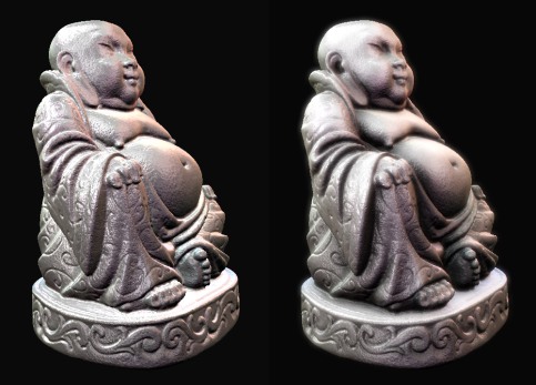
The spinning Buddha (but you can’t see him spin here)

This has been a topic of interest for such a long time for me, but I finally got screen-space ambient occlusion working in my engine. Click here to see it in action! As with most graphics rendering techniques, there are many ways to skin a cat, and SSAO is full of them. I have read through so many articles on SSAO, looking to find something that works for me, and that is easy to understand and refine. Any approach you take may or may not work immediately, based on what already know and what resources you have to handle it.

Ambient occlusion is an easy concept to understand. To put it simply, concave areas, such as the corners of a room, will trap some rays from any light that shines on it, so the ambient light is somewhat darker than in other areas. Used in graphics rendering, this can really make it easier to see depth in different spaces, and it makes objects “pop” from the scene.

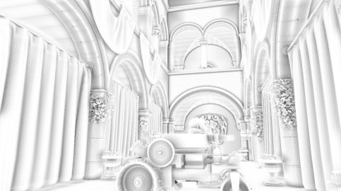
SSAO render target only

Original SSAO render target

The factors involved in computing ambient occlusion are easy to grasp, but I still have trouble breaking down the equations used in some of the approaches. Admittedly I am not very sharp on integration in math, which comes into play for many rendering techniques. But at least my linear algebra is good enough, so I just need to work in those terms to find the approach that works well for me. So I finally came to this article on GameDev, which, true to its title, was easy to figure out and works well for nearly all situations. It includes an HLSL shader that can be applied with few modifications.

To avoid repeating much of what the article says, this SSAO technique requires three important sources of data: normals in view space, positions in view space, and a random normal texture. The random normals reflect 4 samples picked from a preset group of textured coordinates (neighboring samples) which are rotated at fixed angles. The formula in the article attenuates the occlusion linearly, but you can choose to put your own formula if you want a quadratic attenuation, or cubic, etc.

Tweaking the results

A few changes were made to the original shader code to be compatible with my program. First, I don’t have a render buffer that stores view-space position, so the getPosition function needed to be replaced. We can reconstruct world space position from depth using the inverse of the camera’s view and projection matrix, and to get it into view space coordinates, multiply it with a view matrix:

float3 getPosition(in float2 uv)
{
	float depth = tex2D(depthSampler, uv).r;

	// Convert position to world space
	float4 position;

	position.xy = uv.x * 2.0f - 1.0f;
	position.y = -(uv.y * 2.0f - 1.0f);
	position.z = depth;
	position.w = 1.0f;

	position = mul(position, invertViewProj);
	position /= position.w;

	// Convert world space to view space
	return mul(position, ViewMatrix);
}

Probably not the fastest way to get view space from depth, but this code is written with readability in mind. The output image should be four different-colored rectangles evenly dividing the screen, which are the float values of the positions as color. What these colors are depend on the coordinate system you’re using (which is important to know as we’ll soon find out).

After this, I still noticed that the ambient occlusion output seemed to be right, but the values are inverted, so I get a grayscale negative of what is expected. So just subtract the final occlusion value from 1, and we’re good to go:

ao /= (float)sampleKernelSize;
return 1 - (ao * g_intensity);

But why do we need to do this? The reason is that the coordinate system used in XNA is right-handed, while the coordinate system in Direct3D is left-handed. The Z-axis usually points to the camera in XNA, meaning that the positive Z values are behind you, but in Direct3D they lie in front of you. The article was written with DirectX in mind, so users of XNA (and OpenGL if you choose to port the code) will have to invert the occlusion term when it’s returned. This corrects the output given from the normals flipped the other way in view space.

Finally, I removed some of the calculations involved in computing the occlusion, which are the bias and occlusion intensity. The width of the bias didn’t really do anything that I can see any change, and the intensity has been moved out of the the occlusion function and done once in the very last line, which gives the same results as repeating the multiplication by the intensity for each sample.

Final considerations

Your mileage may vary with this shader. To get the best results you’ll have to experiment in tweaking the parameters. The radius variable would work well between values of 2 and 10, depending on how much you scale your objects. Values much higher than this will be expensive to compute. The occlusion is best seen with the intensity set between 0.5 to 1.5, and the distance scale kept low, between 0.05 and 0.5.

SSAO comparison

Left: without SSAO. Right: with SSAO and bloom

Of course, you may want to apply your own blur filter to remove the noise from the AO render. This noise pattern is from the random normal texture, and it stays fixed to the screen when the camera moves. I was able to get reasonable framerates with a full-screen render and a Gaussian blur applied to the AO. Some light “halos” are visible as a result from the blur, but they are not large enough to really distract from the view. What’s especially important to know is that the normals from your normal map must be correct in order to get good results, otherwise objects will be darkened in odd places. But that goes without saying that we’d already notice strange lighting with incorrect normals.

Sources

Project overhaul

Well, I’ve gotten to the point where I’m satisfied enough with my engine to get some actual game coding done. There are still issues related to shadow rendering but those can be worked on alongside everything else. Right now I’m taking a look at everything from a top-down view and planning to trim down the engine to a leaner size. I will talk more about my game project in a later post… just don’t expect it to be groundbreaking or anything like that 😛

For the sake of completion, I don’t want to get carried away with a one-size-does-all engine that has more than what I truly need. This has been an ongoing learning project lasting over two months, and I feel like it’s come pretty far. The engine isn’t immensely huge- I am focusing on a lightweight design- but now that I’ve worked on it for this long, I have gotten a better idea of what works for my upcoming game, and what I can take out so I don’t wind up with something too big and general-purpose.

The rendering library

The biggest change I made in the past week or so is moving all the rendering code into its own library project. It can finally be considered something of an engine, or at the least, a rendering library. For so long I had just a MeteorEngineDemo project, which is the “game” that uses the renderer, and MeteorEngineDemo.Content which grouped all the effect files from the renderer, and meshes used by the game. Having looked at other open-source projects focused on rendering engines in the past, I knew that this wasn’t going to work in the long run. This is just modular programming 101 here. The effects and rendering logic are part of the engine and irrelevant to whatever content you’ll use for any program, and I gotta follow the DRY principle.

After moving the rendering code into its own project, I now have a library project called MeteorEngine, which is referenced by the MeteorEngineDemo, and the library in turn references MeteorEngine.Content. That last one contains all the content that the engine needs to use (effect files, special meshes, etc). That way, all the content can be compiled and added automatically into a separate content folder that’s used by the MeteorEngine.dll at runtime. These projects will probably be renamed from “MeteorEngine” to “MeteorRenderer” since I’m not concerned with building something that handles all sorts of game logic, and to make it clear that it’s for graphics only.

Now my workflow is greatly improved- I can add a reference to this library with any other project I’m working on, while still being able to update the library’s source, and all the updates are reflected in all the other projects referencing it. Of course, this leads to the downside of making sure that all the code in my projects will still work with the library, but I’m doing a fairly good job in separating the rendering logic from everything else.

Variance shadow mapping didn’t prove flexible enough for my needs so I rolled back to using a standard shadow mapping technique in orthogonal space. The shadow is manually filtered thanks to some code from XNA Info. Also, the renderer now uses two HdrBlendable render targets, one for light accumulation, and the second one is for compositing the completed image (before post-processing). These gave me a bit of trouble, since they require a Point filter and they threw off my texture sampling states, causing crashes on startup or textures to display incorrectly. To my surprise, they didn’t seem to impact the rendering performance a whole lot. As an added bonus, I also switched to using the Nuclex font importer for drawing better-looking SpriteFonts.

Performance

So you’re curious to know how well it does, huh? Well, here’s a quick overview of my specs. My home/testing computer, which has a Radeon HD 4670 series video card, an Intel Core 2 Duo E4500 with 3 GB of ram. So it’s nothing close to being mindblowing and probably somewhere in the mid-range as far as video specs go. I also have a Macbook but unfortunately I can only use the Reach profile on there :-/

Okay, so this pic isn’t HD resolution, but check out dat framerate:

Don’t mind the zero triangle count in the readout- I gotta fix that soon. Since it’s light pre-pass, geometry is rendered at least twice. Three times actually, to project the shadow mapping. Post-effects added are FXAA, depth of field, and light bloom in that order.

At 720p it’s still a respectable framerate at 124fps, but with the effects disabled and switched to deferred rendering mode. With effects enabled, it hovers just below 80fps.

Rendering an entire Sponza model is slower- between 65 and 70 fps with one 2048 x 2048 shadow render target. This is mostly to do with the fact that it requires a lot more draw calls-  the model is made up of almost 400 different meshes, and culling each brute force also takes time. It may be more efficient to render if I merged some of the smaller meshes together and re-export the model, but I’d rather move on and create my own models.

Cutting down the code to size

My design for this library just didn’t spring up from the moment I started. Over a year ago, when I was learning from tutorials on DirectX, I came up with a low-level design for a rendering system. I drew it on a sheet of paper, emphasizing the most important connections with the components (sheet coming later!).

The diagram includes some non-rendering components, the game state management (the AppState and Statemanager), which I added to better visualize how it integrates with the whole program. I also got too carried away with static classes, which are probably not necessary for the design. But this is the basis of the design for my current rendering engine, and now that I look back on it, I want to reduce it down to these bare components.

Some of these components will differ from the original design. Effects will be part of a SceneRenderer class, not the Scene class. The entry point of the renderer (Display) will only exist to load up the SceneRenderer and RenderProfiles, and plug in Scenes and Cameras to it. Also, I won’t even need anything like a ResourceMaker in XNA, because the ContentManager and content pipeline take care of everything in there.

To this end, there will also be a clearer separation of data and data processors. I already have this in place with Scenes and SceneRenderers, as the Scenes are just containers for lights and models. This allows me to make some further refinements to the code:

  • Separation of data and its processing systems
  • Changing data objects from reference types to value types wherever possible (on the other hand, it makes little sense to have value type objects that contain reference types)
  • Reducing allocation of memory as per one of the paths to minimize garbage collection. This would include, for example, less resizing of lists for meshes, visible instances, etc. A lot of this makes more sense on Xbox 360, which I don’t have, so unfortunately I can’t really test this to the fullest.
  • Condensing some related objects to a single, but still manageable system. For my game, I’m set on what specific rendering systems to use, so I could trade away some flexibility for more simplicity.

Experimenting with more advanced HLSL is also an option. With classes fully supported in Shader Model 3.0 and XNA as confirmed by this forum post, it can make things more interesting for creating shader frameworks based around deferred rendering. With them we have more ways to manage reusable code and abstraction in shader functions. Here’s a really good article thats shows how function pointer behavior can be done- fully compatible with Shader Model 3.0! To those not used to OOP in HLSL it’s a big eye opener in designing shader code.

So now that it seems like I’m on the final stretch of working on this as a standalone project, it’s time to battle-test it. I already made another project which will be the “new version” of my game, and threw in my rendering library along with it. The screenshots you saw above are taken from that project. For now it’s going to be a matter of adding my own content and whatever game code I could reuse from the old project. As I’m working on my game, the rendering library will also keep changing along the way.

Skinned animations and shadows now in place

The Meteor engine is starting to come into its own with two new important features. I have now intergrated skinned animations and shadows into the rendering. In comparison, adding some good looking directional shadows was fairly easy. There was just a lot of redundant drawing code to clean up and make it easier to adjust the shadows. The mesh animations are a different problem altogether. Both presented some good challenges for me, and still have problems I need to overcome.

Skinned Animations and Blender

The skinned animation feature is working but still underdeveloped- for one thing, they only link to the default (first) animation clip, and I only have the Dude model to test it on. This one was easy to import because it was already made for a skinned animation sample. But making another compatible model like this proved to be no easy task.

I have a greater appreciation for what the 3D artists do, because getting models animated and exported properly has proven to be a huge hassle. Having took a course on it before, I’m decent with 3D modeling tools, including Blender. But actual modeling of props and characters is a huge time suck, so I’m just making small adjustments to models I found elsewhere.

I have tried binding an armature (a skeleton in Blender) to another test model and have been unable to assign blend weights automatically. So instead I took the much longer route of manually painting blend weights to each bone myself. With some models this became tedious, because some have underlying nooks and crevices that makes it hard to paint properly, and I have to zoom and turn the camera at all sorts of odd angles.

The issue is that XNA will not accept any skinned models if even one vertex has a weight of zero, meaning that all vertices need to have some influence to be moved by at least one bone. When having to deal with character meshes with several thousands of vertices, assigning weights automatically is a great time saver, but only when it works properly. I decided to just stick with the Dude model for now and make do with a simple flexible tube that’s not complex in shape. Right now I’m busy cleaning and improving the rendering code, but I’ll get back to the animated mesh problem eventually.

Animating the Models

J. Coluna’s recent rendering sample helped me with applying bone transformations on the GPU. It’s just a short set of matrix additions to apply all the transformations in the matrix stack. I created two separate vertex shader functions to deal with skinned and non-skinned meshes, the former having the extra matrix calculations. Skinned meshes and static meshes are grouped in different lists to organize the rendering. I suggest that you check his solution out if you want to do something similar with combining animation with your own shaders.

So the animation code seems manageable, but my implementation is  clumsy. For every effect technique that renders a mesh, I copied that technique, with “Animated” added to the name, and replaced the vertex shader with the one supporting bone animations. This made my already huge GBuffer / uber-effects file a bit longer, and I have to constantly copy more stuff in it if I need to make a shader for another rendering style. Any missed techniques will make the program crash since it fails to find one with the proper name. This is not a big worry since I’m the only one working on the code, but I do want to use a better way to handle skinned models in the shaders and cut down on the code a bit.

For now, though, my biggest hurdle on skinning is not technical- it clearly lies in the fact that I gotta learn how to use Blender more effectively to skin and animate whatever models I want to.

Variance Shadow Mapping

I briefly covered this topic a in the last post, and I was still experimenting with the results that it will produce when integrated into the engine, but after a lot of tweaking parameters, it’s finally starting to look great. To my surprise, the shadows did not fade out with close proximity to the shadow casters, so the objects don’t look like they’re floating. I’m okay with not having very defined shapes for the shadows all the time.

You could still get some good quality rendering just a single 512×512 map with the Sponza scene, and with enough saturation, the edges look great without a lot of noticeable bleeding artifacts that come from using screen-space blur. With results like these, I could hold off implementing SSAO for a while. Here you can see a screenshot with only the directional light and shadows applied:

Shadowing only works with directional lights for now. It has a “casts shadows” property which can be set to true or false, and all lights that have this turned on will be considered for drawing shadow maps. A cool feature is that, for artistic purposes, you can have the intensity of the shadows adjusted independently from the brightness of the light that produces them. This means you can dim or darken the shadows as the light angle changes, or even have a “dummy” directional light that is completely colorless (no light) but you can use its directional and distance properties to cast shadows overhead. It is more possible to create visually striking scenes this way.

A Few Kinks in the Armor

For now, I am using a separate Camera object to represent the light’s point of view, as with any shadow mapping technique. But the camera’s orientation is not yet tied with the light’s viewing direction. This means that the camera’s orientation is essentially useless and does not factor in at all with the rendering of the depth map and shadow projection. But I need this information to correctly cull the scene objects from the light’s point of view. As it is, shadows pop in and out as the “main” camera moves, because the shadow mapping effect is rendering only the objects as visibly seen from that camera. Once I figure out how to assign shadow casters and receivers for the appropriate light, that problem should go away.

Another problem I noticed came about when I combined the skinned animation shader with the shadow mapping effect. Those animated models are giving me a hard time! Here, the Dude model is mostly dark, with light spots in random places, even when they’re not supposed to be light. They move a bit and generally stick around the same areas when he’s walking, which just look odd in the final render.

At first I thought that I didn’t correctly calculate the normals for the shader, but then I realized that the shadow map projection doesn’t take normals into account at all, so there’s definitely something weird going on with how the shadows are being projected onto them.

What Else I Can Improve

Other than these major issues, I’m pretty happy with how these features brought more life into the renderings. There are some pending goals that I plan to take on next week, and at least get two of these done:

  • Better implemenation of cameras for directional lights
  • Possible parallel-split variance shadows, for even better quality
  • An option to use more traditional shadow mapping with some screen-space blur
  • Support hardware instancing of meshes
  • A straightforward .obj file splitter program to break up large .obj models into smaller files (I’ll release it to the public)
  • Frustum culling from the light’s point of view

I’ll be sure to cover at least one of these topics soon, and continue providing samples related to these.

XNA 4.0 variance shadow mapping

I’ve just updated and refined another code sample from XNA Community, from XNA version 3.1 to 4.0. This one is on variance shadow mapping, which is basically a way to get shadow maps that are filterable- that is, you can apply any kind of texture filter onto the shadow mapping image to give it a smoother look. Optionally, and usually, a Guassian blur filter is applied. Together, variance shadow mapping improves the visual quality of the shadows as well as giving more leeway to the size and number of textures needed to produce good results.

In the sample code, the program uses one 1024×1024 texture to produce the shadow map, and applies a two-pass filtering technique for Gaussian blur. This blur is not done in screen-space, but because the original shadow map can be filtered, it is almost indistinguishable from a screen-space blur, which will produce leaking artifacts if done with normal shadow maps.. Most of the heavy image computation is done in this step.

The shadow uses a 2-channel 32-bit texture for the depth map, in contrast to a single floating-point texture format used in conventional shadow mapping. This allows us to store two “moments”, which are simply the depth and the squared depth stored in the depth texture. From here we are able to calculate the mean depth and variance of the given pixel in the map. One noticeable drawback to variance shadow mapping is light bleeding among shadows where the shadow casters are of very different depths. An easy fix to reduce this effect would be to raise the shadow amount by a certain exponent, but raised too high and the shadows dampen too much.

I plan to use some form of variance shadow mapping to my graphics engine, but in the meantime I’ll try to make improvements on it, in order to remove the light bleeding more effectively. But in the meantime, you can download current sample project here, compatible with XNA 4.0.

References:

Bounding boxes for your meshes

While making progress with my rendering engine, one of my goals for this week is to finally implement some kind of frustum culling for the meshes. I could have taken the easier route by only using the pre-built bounding spheres with every 3D model loaded in an XNA program, but I wanted to get tighter-fitting bounding boxes instead. They simply work better for selection and picking, and plus more meshes are culled out of the frustum, which means less false positives and less geometry being rendered off-screen.
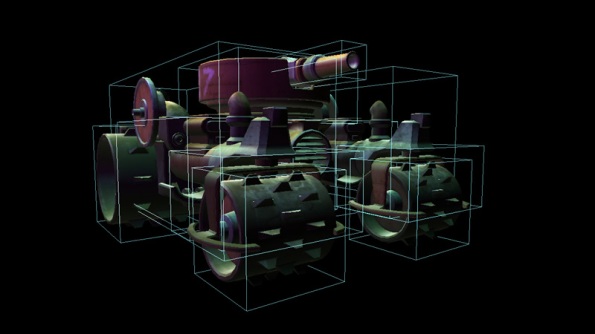
Mesh bounding boxes

Tank model with boxes enclosing all of its parts

Today I have finally finished the first major step, creating the bounding boxes. Simply figuring out how to perfectly create the boxes proved to be a frustrating chore. It wasn’t really the formula to create a box from points that was the difficult part, but getting the correct set of points from each mesh. This required a proper understanding of the GetData method for the VertexBuffer object of each mesh part. I will show you how I obtained the data to create those boxes.

There are so many requests online for wanting to figure out how to correctly build a bounding box for a mesh object, and a lot of those queries are answered with outdated information, or they don’t turn out to be the best case for that particular user. I’ve browsed through several solutions and a few code samples of how to create them, but they were not working for me. Sometimes the program crashes with an OutOfBounds exception, and other times, the boxes are obviously misaligned with the meshes, even after double checking that the correct transformations are in place. But I finally came up with a solution that used a combination of a few approaches to read and add the vertex data.

Building The Box

Bounding boxes are just simple geometric boxes, and be represented with two three-dimensional points, the minimum and maximum coordinates. The distance between those two points is the longest possible diagonal for the box, and the points can be thought of as the upper right corner in the front of the box, and the lower left corner in the back. These boxes are usually created as mesh metadata, during build time or when resources are initialized. It would be very costly to read the vertices and update the bounding boxes on every frame- besides, you should use matrix transformations to do that. Here is how we would usually initialize a mesh model:

public MeshModel(String modelPath)
{
	/* Load your model from a file here */

	// Set up model data
	boundingBoxes = new List<BoundingBox>();

	Matrix[] transforms = new Matrix[model.Bones.Count];
	model.CopyAbsoluteBoneTransformsTo(transforms);

	foreach (ModelMesh mesh in model.Meshes)
	{
		Matrix meshTransform = transforms[mesh.ParentBone.Index];
		boundingBoxes.Add(BuildBoundingBox(mesh, meshTransform));
	}
}

This would typically go in the constructor or initialization method of the class used to keep your model object, and all of its related data. In this case, we have a List of BoundingBox objects, used to keep track of all the upper and lower bounds for all meshes the model might have. Possible uses may be to do basic picking and collision testing, and debugging those tests by drawing wireframe boxes on the screen (which I will cover further in this article).

You may have noticed the BuildBoundingBox method in adding to the BoundingBox list. This is where we will create an accurate, tight-fitting box for every mesh, and to do this we will need to count all the vertex data for all its mesh parts. It requires a ModelMesh object and a Matrix object which is the bone transformation for that particular mesh.

This method will start out by looping through all the mesh parts to keep track of the maximum and minimum vertices found in the mesh so far, and returns the smallest possible bounding box that contains those vertices:

private BoundingBox BuildBoundingBox(ModelMesh mesh, Matrix meshTransform)
{
	// Create initial variables to hold min and max xyz values for the mesh
	Vector3 meshMax = new Vector3(float.MinValue);
	Vector3 meshMin = new Vector3(float.MaxValue);

	foreach (ModelMeshPart part in mesh.MeshParts)
	{
		// The stride is how big, in bytes, one vertex is in the vertex buffer
		// We have to use this as we do not know the make up of the vertex
		int stride = part.VertexBuffer.VertexDeclaration.VertexStride;

		VertexPositionNormalTexture[] vertexData = new VertexPositionNormalTexture[part.NumVertices];
		part.VertexBuffer.GetData(part.VertexOffset * stride, vertexData, 0, part.NumVertices, stride);

		// Find minimum and maximum xyz values for this mesh part
		Vector3 vertPosition = new Vector3();

		for (int i = 0; i < vertexData.Length; i++)
		{
			vertPosition = vertexData[i].Position;

			// update our values from this vertex
			meshMin = Vector3.Min(meshMin, vertPosition);
			meshMax = Vector3.Max(meshMax, vertPosition);
		}
	}

	// transform by mesh bone matrix
	meshMin = Vector3.Transform(meshMin, meshTransform);
	meshMax = Vector3.Transform(meshMax, meshTransform);

	// Create the bounding box
	BoundingBox box = new BoundingBox(meshMin, meshMax);
	return box;
}

A lot of important stuff just happened here. First is the setting up of vertexData, which is an array of VertexPositionNormalTexture structures. This is one of several built-in vertex structures that can be used to classify and organize vertex data. In particular, I used this one because my vertex buffer contains position, normal and texture coordinates up front, and no color data. It will help us determine where our position data is located, which is the only data needed to create our box.

However, this is not enough to assess the alignment and structure of the vertex buffer. We also need to know the vertex stride, which is simply the number of bytes that each vertex element contains. This number will vary depending on how your meshes are created and what data was imported, and it can even vary with each vertex buffer. With this piece of info, stepping through the vertex buffer should now be straightforward, with the vertex stride ensuring that we get accurate data. The vertexData gets sent to an inner loop where we simply examine each vertex, seeing if we have found a new minimum or maximum position. By default the minimum and maximum are set to extreme opposite values.

After the loop is done, we now have the only two vertex points that matter, and these are transformed by the mesh’s parent bone matrix. Finally, a new bounding box is created and returned from these two points. Optionally you can also choose to create a custom bounding sphere from the bounding box.

Drawing the boxes for debugging

Now with our boxes stored in place, let’s put them to some use. We are going to draw the bounding boxes that correspond to the meshes for each model. If they are drawn together with the model, the wireframes should hide behind solid objects.

Every BoundingBox has a Vector3 array which represent the eight corners of the box. The first four corners are of the front side, and the last four corners are the back. We are going to use a line list to draw the 12 edges representing the box. Each line connects a pair of corners, and the following array will form the edges:

// Initialize an array of indices for the box. 12 lines require 24 indices
short[] bBoxIndices = {
	0, 1, 1, 2, 2, 3, 3, 0, // Front edges
	4, 5, 5, 6, 6, 7, 7, 4, // Back edges
	0, 4, 1, 5, 2, 6, 3, 7 // Side edges connecting front and back
};

Now in the drawing loop, we will loop through the bounding boxes for the model, set the vertices and draw a LineList for those using any desired effect. This example uses a BasicEffect called boxEffect.

// Use inside a drawing loop
foreach (BoundingBox box in boundingBoxes)
{
	Vector3[] corners = box.GetCorners();
	VertexPositionColor[] primitiveList = new VertexPositionColor[corners.Length];

	// Assign the 8 box vertices
	for (int i = 0; i < corners.Length; i++)
	{
 		primitiveList[i] = new VertexPositionColor(corners[i], Color.White);
	}

	/* Set your own effect parameters here */

	boxEffect.World = Matrix.Identity;
	boxEffect.View = View;
	boxEffect.Projection = Projection;
	boxEffect.TextureEnabled = false;

	// Draw the box with a LineList
	foreach (EffectPass pass in boxEffect.CurrentTechnique.Passes)
 	{
		pass.Apply();
		GraphicsDevice.DrawUserIndexedPrimitives(
 			PrimitiveType.LineList, primitiveList, 0, 8,
			bBoxIndices, 0, 12);
	}
}

In practice, you should make sure that if you transformed the scale, position, or rotation of your model, to apply the same transformations to all the boxes as well. Also, remember that it is best to move any shader parameters that won’t change outside of the drawing loop, and set them only once.

That’s all there is to it. This should render solid colored wireframe boxes, not simply around your models, but in all the meshes they contain.